On a medium or large industrial UAV, the battery is no longer just a removable source of watt-hours. It is part of an aircraft electrical system: packs, contactors, pre-charge circuits, converters, buses, harnesses, sensors and software all decide whether stored energy can still reach the equipment that keeps the aircraft under control.
That distinction is easy to miss in a catalogue. Two battery packs may look redundant while still feeding one contactor, one power-distribution board and one DC/DC converter. If the common path fails, the second pack may have energy and no safe route to the flight computer. A genuine dual-bus design is therefore not a battery model. It is a vehicle-level architecture with defined failure boundaries.
The correction matters most on aircraft carrying expensive sensors, operating beyond visual line of sight or flying over infrastructure. An avionics brownout can erase navigation, command-and-control and recovery logic in the same instant. Keeping a small essential bus alive does not guarantee continued lift, but it can preserve the information and control authority needed to execute the aircraft’s designed emergency response.
First, separate four claims that are often sold as one
Engineers use the word redundancy carefully; marketing often does not. A second pack can mean more energy, more discharge capability, an avionics backup or a truly independent propulsion channel. Those are four different claims. The airframe may need one of them, several of them or none of them, depending on its operating risk and emergency concept.
Two packs on one bus can be a sensible propulsion choice. Current sharing may reduce stress, and one open pack may leave the other connected if the combining hardware is designed correctly. Yet the bus, master contactor, pre-charge path or avionics converter can remain a single point of failure. That arrangement should be described as dual-pack propulsion, not automatically as dual-bus power.
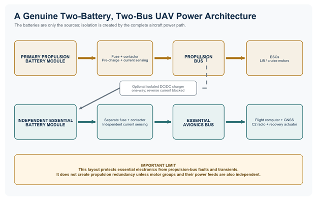
A dual-battery, dual-bus arrangement goes further. One protected source feeds the propulsion bus; another independently protected source feeds the essential avionics bus. A payload may sit on a third, shed-able rail. Continued propulsion after a source fault is a still higher claim: it normally requires independent battery-to-motor paths, defined motor groups or another recovery system. An avionics backup battery alone cannot keep a multirotor airborne.
| Architecture | What it really means | The design caution |
| One source, one bus | Propulsion, avionics and payload depend on one main distribution path. | Light and simple, but an upstream fault or severe transient can reach every load. |
| Two batteries, one bus | Two packs are paralleled or switched onto one common propulsion bus. | Can add energy or current capacity, but the common bus, contactor or converter can still defeat both packs. |
| Two batteries, two buses | Propulsion and essential avionics use separately protected sources and distribution paths. | Protects control electronics; independence must be proven through wiring review and fault injection. |
| Independent propulsion channels | Separate battery-to-motor paths feed defined motor groups or another recovery system. | This is the additional step needed when the safety case requires continued lift after a propulsion-source fault. |
Architecture labels in this table are functional descriptions. Actual fault tolerance depends on converters, protection, wiring, grounding, software and test evidence.
At industrial scale, mission phase changes the electrical problem
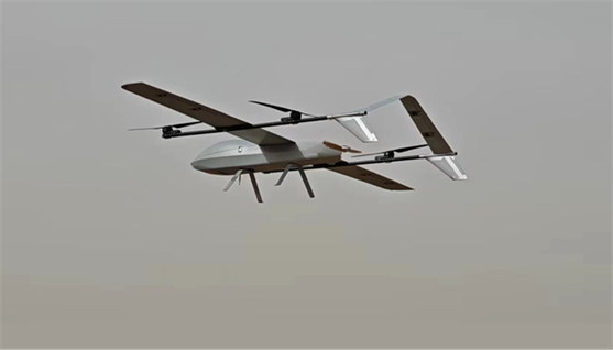
A published 2025 design study gives a useful real-aircraft reference. The researchers built and flight-tested a 30 kg composite-wing electric FW-VTOL with a 5 m wingspan. The measured aircraft carried 10.7 kg of battery and a 3.67 kg payload. These figures are not a market average, but they are much closer to the class of custom industrial aircraft under discussion than a 6S hobby pack on a tabletop. [1]
Its mission table is even more revealing. Transition required 10.03 kW for 0.5 minutes; VTOL ascent and descent required 6.35 kW for 5.5 minutes; fixed-wing cruise required only 0.57 kW, but for 90 minutes. Transition power was about 17.6 times cruise power, while cruise consumed the largest energy share at 855 Wh. The pack therefore had to satisfy a brief power problem and a long energy problem in the same flight. [1]
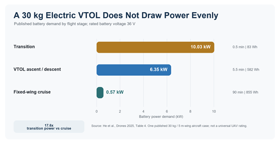
The paper also records a detail that catalogue calculations often omit: the actual battery mass was 4.6% higher than the estimate because of wiring and packaging. On a medium or large UAV, harness length, contactors, enclosures, cooling paths and structural supports are not rounding errors. A second bus adds real mass; it must earn that mass by containing a defined fault or preserving a defined emergency function. [1]
What a real dual-bus installation must contain
The primary propulsion path normally includes its own pack or pack set, fuse, contactor, pre-charge circuit, current measurement and distribution hardware before it reaches the ESCs. The essential path needs its own battery, protection, current measurement and bus feeding only the equipment required for the emergency concept: flight computer, navigation sensors, command-and-control radio and any actuator or recovery device needed for a controlled outcome.
If the propulsion system charges the essential battery in normal operation, the link should be designed so that a propulsion-bus collapse, converter short or reverse-current event cannot drag down the essential source. An isolated one-way DC/DC charger is one possible implementation. It is not the only one, and the correct topology depends on voltage, grounding, electromagnetic compatibility and the aircraft’s safety analysis.
The drawing must then survive the installation. Two sources routed through the same master switch are not independent. Two harnesses tied to the same sharp bracket share a chafing hazard. Two battery modules in one unvented compartment may share a thermal event. A single BMS controller that can open both contactors after one sensor fault can recreate a common failure in software. Independence has electrical, mechanical, thermal and logical dimensions.
Avionics continuity is not propulsion redundancy
This is the most important limit in the article. An essential battery can keep the flight computer awake after the propulsion bus fails; it cannot manufacture thrust. A medium or large multicopter that must remain airborne after one battery-source fault needs independent propulsion channels, enough remaining rotor authority, fault detection and validated control laws. A fixed-wing VTOL may have a different emergency path once it is safely in wing-borne flight, but that depends on altitude, configuration and the cause of the failure.
The benefit of the essential bus is still substantial. It can preserve telemetry, position, fault records, navigation and command reception while the aircraft sheds payloads, deploys a recovery device, glides, diverts or performs a controlled landing. It turns a total electrical silence into a managed degraded state—but only if the emergency sequence was defined before the battery was sized.
Research numbers help—if their scale and cause are kept straight
A 2026 Journal of Energy Storage paper modelled a dual-battery, dual-bus VTOL system that separated propulsion from avionics. In the study’s small-to-mid-scale 6S model, changing the propulsion pack from 6S1P to 6S2P raised minimum pack voltage by 2.0 to 3.5 V and reduced peak core temperature by 27.9 to 37.9 C across the analysed missions. Those are model results for the stated platform and assumptions, not values to scale directly into a 30 kg or 50 kg aircraft. [3]
The cause also matters. The voltage and temperature improvements came from parallelising the propulsion pack and reducing current per cell. They were not created by the avionics battery. The same paper supports two separate engineering decisions: size the propulsion pack against the mission’s electrochemical and thermal demands, and isolate essential electronics so propulsion disturbances are not allowed to become avionics resets.
NASA’s X-57 provides a useful larger-aircraft analogue, although it was a crewed experimental aeroplane rather than a UAV. Its published design used two 13.8 V converter buses and a lithium-iron-phosphate essential battery intended to keep safety-of-flight loads powered if both primary converters were lost. [4]
A later NASA lessons-learned presentation warned that negative noise spikes of 3 to 5 V could switch off a 13.8 V avionics system, and recommended redundant sources, load shedding and an essential bus with backup power. These aircraft are not interchangeable, and none of the figures above is a ready-made pack specification. What transfers is the method: define the mission, identify essential loads, map every distribution path, establish the degraded state and verify it with measured voltage, current, temperature and event data. [5]
The documentation standard is moving toward system evidence
EASA’s June 2026 Easy Access Rules for UAS show how serious the power-system description has become. The guidance asks applicants to describe regulators, switches, buses and converters; state continuous and peak motor power and current ranges; explain whether propulsion has a separate source; and provide a system-level electrical-distribution diagram. For backup power, it asks what remains powered, what is shed, how long the source operates and which assumptions support that time. [2]
EASA does not prescribe one universal dual-bus topology for every industrial UAV. Its value here is the evidence discipline: a label is not enough. Singapore’s civil-aviation guidance makes a related point for BVLOS assessment, calling for critical power supplies to be monitored and for the failure of one energy source not to interfere with the remaining sources. Different jurisdictions apply different rules, but both documents push the conversation from component claims toward system behaviour. [6]
What a B2B battery supplier should deliver
For a custom battery programme, the first document should not be a price sheet. It should be the aircraft power map and mission profile. The pack supplier needs to know maximum take-off mass, flight stages, rated bus voltage, peak power and its duration, continuous cruise power, payload demand, temperature range, landing reserve and the fault state the aircraft must survive.
- Specify each source separately. State total and usable watt-hours, nominal and operating voltage, rated capacity, continuous current, peak current and permitted peak duration for both the propulsion source and the essential source.
- Define the environmental limits. Give the validated working-temperature range, recommended charge-temperature range, cooling assumptions, altitude effects and derating rules rather than a single ideal-room-temperature rating.
- Make BMS evidence usable. Identify cell-voltage and multi-point temperature sensing, current measurement, cycle count, state-of-health method, data logging and fault records. State which faults open which contactor and whether one controller can disconnect both sources.
- Document the interfaces. Define pre-charge, contactor drive, fusing, reverse-current blocking, converter input windows, communication protocol, connector ratings and grounding. A battery drawing without the aircraft interface is incomplete.
- Test the failure boundary. At low state of charge and the coldest relevant condition, apply the worst credible propulsion step load; interrupt each source; test a converter short or failed blocking device; and record both buses fast enough to capture transient voltage and reset events.
- Close with aircraft-level proof. Report the aircraft model, mass, payload, flight profile, weather assumptions, starting state of charge and landing reserve. Bench data qualifies components; flight data validates the installed system.
The honest sales claim
A medium or large industrial UAV may use two identical propulsion packs, a large propulsion battery plus a smaller essential battery, or several independent modules feeding separate motor groups. None of those layouts is automatically superior outside its mission and safety case. The credible claim is narrower: the sources and buses were chosen for defined loads, defined faults and a measured degraded mode.
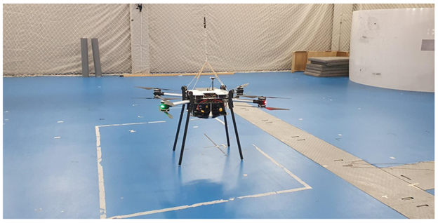
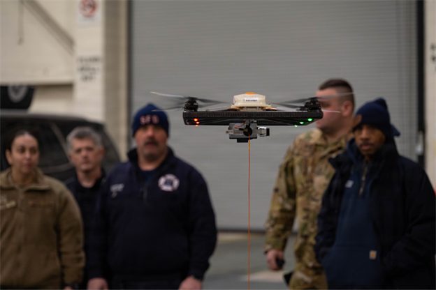
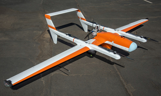
This is also why product photography is weak evidence for a redundancy claim. A pair of batteries on a white background cannot prove bus independence, and a small exhibition drone cannot represent a medium or large custom aircraft. The useful evidence is the aircraft-scale photograph, the power-by-flight-stage data, the distribution diagram and the fault-test record. Energy density still matters. At the moment of failure, however, architecture decides whether the energy that remains can still be used.
Sources
4. NASA, X-57 Traction Power and Command Systems Development, ICAS 2024.
5. NASA, X-57 Avionics Architecture: Lessons Learned, ASTM Committee F44 workshop material, 2024.
7. NASA, HQ-90 Arrives at NASA’s Armstrong Flight Research Center, aircraft scale and photo source.