A practical EMI and EMC guide for industrial drone integrators
A UAV can lose GNSS quality, show unstable compass readings, or reset an avionics module when its power system is operating. That makes the battery system worth investigating—but it does not prove that the cells are the source. In a working aircraft, the battery, battery management system (BMS), converters, high-current wiring, electronic speed controllers (ESCs), motors, radios, and sensor layout form one electromagnetic environment.
The reliable way to answer the question is to test the installed configuration under representative loads, record the right signals, and isolate one change at a time. This guide explains the mechanisms, the evidence, and a supplier–integrator workflow that avoids treating every navigation symptom as a battery defect.
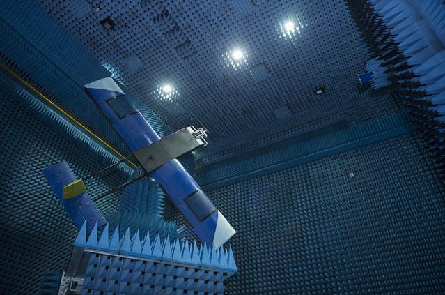
A UAV in ESA’s radio-frequency test chamber. The photograph illustrates aircraft-level RF testing; it is not a battery EMC qualification result. Image: ESA–G. Porter, CC BY-SA 3.0 IGO; resized for layout. · Source page · License
Start with the right distinction
A cell stack is not automatically a radio transmitter. The relevant object is usually the installed power system: cell interconnects and busbars, BMS switching or balancing, DC-DC converters, connectors, harness geometry, return paths, and the nearby ESC and motor installation. Some of these elements create changing magnetic fields; switching devices can also place conducted noise on a shared supply or return. Whether that noise reaches a receiver depends on frequency, current, geometry, shielding, filtering, and the susceptibility of the affected equipment.
EMI is unwanted electromagnetic disturbance. EMC is the system-level question: can equipment operate as intended in its electromagnetic environment, and can it do so without unacceptably disturbing other equipment? External radio-frequency interference (RFI) is another possible cause. A symptom that appears during flight may come from an onboard source, an external transmitter, a poor antenna installation, power-rail sag, software behavior, or more than one factor.
How the power system can couple into avionics
Four paths are useful for an initial fault tree. They overlap in real aircraft, and this list is not a ranking of likelihood.
| Path | What can happen | What to inspect |
| Magnetic near field | Changing current in a high-current loop can bias a nearby magnetometer or compass. The ESCs and motors may be stronger contributors than the battery pack. | Current-loop area, relative sensor position, current and motor-command conditions, compass innovations. |
| Conducted or shared impedance | Switching edges or load transients can travel on shared supply and return conductors, disturbing a receiver, sensor rail, or flight-controller input. | Power and return routing, connector resistance, regulator layout, bus voltage at the avionics connector. |
| Radiated coupling | A noisy converter, harness, or digital subsystem may couple into a GNSS antenna feed or receiver front end if the frequencies and installation permit it. | Antenna/feed routing, receiver status, satellite-specific C/N₀, operating radio states, controlled load changes. |
| Power integrity | Voltage drop or a transient can cause a brownout, restart, or sensor fault that resembles an EMI problem in the flight log. | Synchronized rail-voltage measurement, reset reason, BMS events, current and load step. |
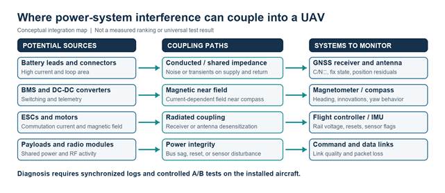
Figure 1. Conceptual UAV power-system coupling map. Arrows show possible paths, not measured causality, severity, or a universal source ranking.
What published evidence does and does not show
There is credible UAV-specific evidence that onboard power and propulsion activity can affect magnetic measurements. It is useful for choosing tests, but it does not provide a universal battery-to-compass distance, a GNSS interference threshold, or a pass/fail limit for every aircraft.
| Published evidence | Useful conclusion | Boundary of the evidence |
| Kuevor et al., Sensors (2023) [1] | A low-cost UAV magnetic-mapping study reports measurable magnetometer noise associated with flight-controller motor commands and examines separation from electronics. | The work concerns its tested vehicles, sensor, controller, and magnetic-mapping task. It is not a fleet-wide GNSS or battery qualification limit. |
| Ge et al., Chinese Journal of Aeronautics (2023) [2] | A study of a small solar/hydrogen hybrid UAV models trajectory-related and DC interference from its hybrid power sources at an airborne magnetometer, and proposes mitigation layers. | Its architecture and modeled/validated case are specific. It should not be generalized into a claim that all lithium packs disrupt compasses. |
| NASA Langley sUAS safety case (2023) [3] | For one BVLOS system, NASA’s analysis lists EMI/EMC ground testing and checks of GPS wiring and antenna mounting among GPS-failure controls. | This is a safety case for a named system and operation, not a universal checklist or regulation for every commercial drone. |
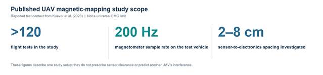
Figure 2. Reported scope of one published UAV magnetic-mapping study [1]. The figures describe that study’s test setup, not a design limit or performance guarantee for another aircraft.
The practical implication is modest but important: magnetic and power-integrity effects are testable; GNSS symptoms still require receiver-level evidence. Track satellite-specific carrier-to-noise density (C/N₀), fix state, antenna and cable condition, and the timing of any drop relative to current, converter state, and radio activity. A compass shift is not proof of GNSS interference, and a GNSS drop is not proof of a bad battery.
Read the symptom before changing hardware
| Observed symptom | Evidence to collect | First separation test |
| GNSS C/N₀ or fix degrades under load | Per-satellite C/N₀, fix and receiver flags, pack current, avionics rail, antenna and cable state, radio transmit state. | Repeat the same static test with propulsion disabled and representative non-propulsion loads; then change only the suspect power component or harness route. |
| Compass heading shifts as throttle changes | Raw magnetometer data, compass innovations, motor commands, current, yaw estimate, and sensor/pack geometry. | Hold the aircraft and test controlled motor/load conditions in a safe fixture; compare with a controlled sensor relocation or harness change. |
| Flight controller or GNSS receiver restarts | Voltage at the equipment input with an appropriately rated, safely connected instrument; reset reason; BMS flags; current waveform. | Check for rail sag, connector heating/resistance, regulator behavior, and brownout records before treating the event as radiated EMI. |
| Intermittent data or command-link loss | Receiver link metrics, packet/error counters, radio channel and transmit state, BMS telemetry activity, event timestamps. | Separate external RFI and antenna issues from onboard conducted or radiated coupling by repeating with radio states controlled. |
A practical integration test sequence
Freeze the configuration first. Record the exact pack and BMS revision, firmware, harness length and routing, connectors, converter models, ESC and motor set, GNSS antenna location, payload, and flight-controller settings. A result from a bench pack with short leads may not represent the production-intent aircraft.
- Establish a baseline with a known-good configuration. Record receiver C/N₀ and fix state, compass data and innovations, flight-controller errors and resets, bus voltage at the avionics input, pack current, BMS warnings, and radio state against a common time base.
- Exercise representative operating states safely: idle, steady load, controlled load steps, converter modes, telemetry activity, and expected radio transmission. Use a fixture or ground test before flight whenever possible; keep propeller and high-current test hazards under the project’s approved controls.
- Change one factor at a time. Examples include pack/BMS variant, harness routing, return path, converter operating mode, or antenna/feed routing. Repeat each comparison enough to distinguish a repeatable effect from normal receiver and environment variation.
- Validate the final production-intent installation. A component-level emissions check can help isolate a source, but aircraft-level acceptance depends on the assembled geometry, harnesses, equipment, and operating states.
Set acceptance criteria before testing. There is no single universal GNSS C/N₀ drop, compass deviation, separation distance, or battery current that can be used as the pass/fail limit for every UAV. Derive limits from the receiver and flight-control requirements, safety assessment, operational environment, and applicable approval basis.
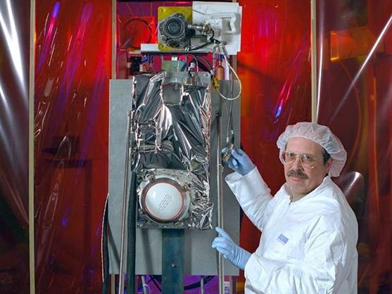
NASA Glenn technicians conduct electromagnetic testing on a Hall thruster system in the EMI laboratory. This image illustrates lab context; it is not a UAV battery test. Image: NASA Glenn Research Center.
Design and supplier practices that reduce surprises
Begin with installation geometry and evidence. Keep high-current supply and return paths close together where electrical, thermal, mechanical, and safety constraints permit; this reduces loop area, though it is not a substitute for measurement. Route sensitive GNSS antenna feeds and low-level sensor wiring away from switching power and propulsion conductors where practical. Follow the receiver and airframe manufacturers’ installation guidance, and do not apply a generic keep-out distance as if it were a certified limit.
Ferrites, shields, filters, and added spacing can help in a diagnosed case, but each can introduce trade-offs such as voltage drop, heat, mass, altered antenna behavior, or new resonances. Make the smallest controlled change that addresses the observed coupling path, then repeat the test. A static compass calibration can correct fixed offsets; it cannot reliably cancel a field that changes with current, switching state, or aircraft configuration.
For battery suppliers, the useful technical exchange is specific: disclose relevant BMS switching and balancing behavior, converter or telemetry interfaces, harness and return-path constraints, revision control, and any test configuration behind an EMC claim. For integrators, provide the intended load profile, receiver and antenna installation, wiring drawings, and defined acceptance criteria. A pack-level statement should not be presented as aircraft-level EMC qualification.
Certification context
The FAA’s AC 20-190 identifies SAE ARP 60493 and EUROCAE ED-248 as recommended practices for showing compliance with specified aircraft certification provisions. The circular says it is not mandatory and is not itself a regulation; its guidance is aimed at applicants whose certification basis requires the provisions it identifies. It also says system EMC scope should reflect aircraft category, change complexity, and safety impact. This is useful context for formal aircraft programs, but it is not a blanket commercial-UAV requirement. Confirm the applicable rules and approval basis for the aircraft and market in question.
NASA Glenn describes tests involving shielding effectiveness, filtering, grounding, and final qualification in flight configuration (laboratory capabilities). These are examples of available EMC test methods, not a prescribed test plan for every battery-powered drone. A competent EMC laboratory can help turn a specific failure mode and acceptance requirement into a controlled test plan.
Questions integrators should ask before approving a pack
- Which BMS, converter, balancing, and telemetry functions switch during normal flight, and under what operating conditions?
- What pack revision, harness length, return path, load, and sensor placement were used for any reported EMC or magnetic test?
- Were tests conducted on the pack alone, the battery and power harness, or the fully installed aircraft?
- Were GNSS receiver metrics, compass outputs, avionics input voltage, reset records, and pack events time-aligned?
- What configuration changes trigger revalidation, and who owns the aircraft-level acceptance criteria?
FAQ
Lithium battery and GNSS interference
It can be part of an installed power system that couples noise into a receiver or antenna, but the cell chemistry alone does not establish the cause. Check the BMS, converters, harness, return path, antenna installation, propulsion electronics, and external RFI with synchronized evidence.
Compass changes during motor operation
Motor and ESC current can create changing magnetic fields near the compass. Battery current paths and other electronics may also contribute. The effect depends on the aircraft geometry and operating state, so compare controlled current and sensor data on the actual installation.
Ferrites as a UAV battery EMI remedy
Only if the diagnosed coupling path and frequency range are appropriate for that ferrite and installation. It will not correct a magnetic near-field problem in every case, and it can add electrical or thermal trade-offs. Test the change on the installed system.
FAA AC 20-190 scope for drones
No. It is non-mandatory guidance for applicants addressing specified aircraft certification provisions. It is not a blanket rule for all commercial UAVs. Check the aircraft’s certification basis and operating jurisdiction.
References
[1] Kuevor et al., UAV magnetic-field mapping study, Sensors 23(8), 3897 (2023). Source — magnetometer noise and study setup
[2] Ge et al., hybrid-powered UAV EMI study, Chinese Journal of Aeronautics 36(10), 293–308 (2023). Source — configuration-specific magnetometer case
[3] Coldsnow et al., NASA/TM–20230003007 (2023). Source — UAS BVLOS safety case, Table 11