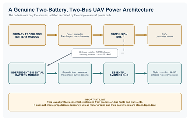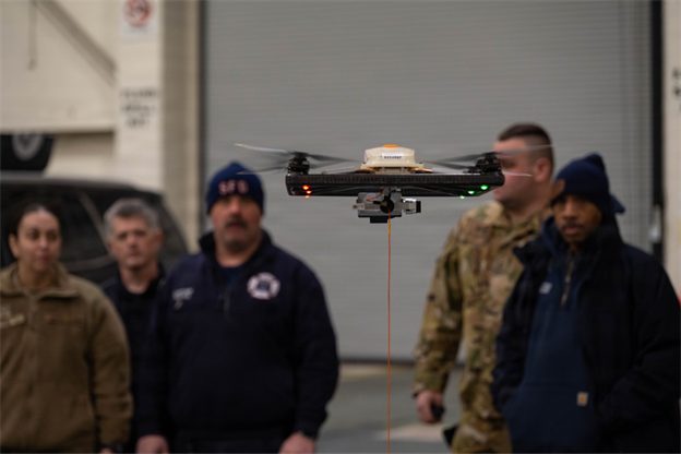
Industrial UAV buyers often compare watt-hours, C-rate and energy density first. Yet the decision that quietly reshapes current, heat, wiring, ESC selection and serviceability is the pack voltage itself.
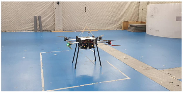
A custom coaxial octarotor during indoor flight testing. This kind of non-standard, power-dense architecture makes battery voltage a system-level design decision. Source: Berra et al. (2024), Drones, CC BY 4.0
In an industrial-drone RFQ, buyers usually compare capacity and discharge rate first. Voltage often appears later, as if it were only a connector choice. That made sense when much of the multirotor component market centred on 6S. It becomes less convincing for aircraft carrying LiDAR, spray tanks, winches or delivery loads, especially when long harnesses and multi-kilowatt propulsion are involved. At that point, voltage is part of the aircraft architecture.
Seen this way, the 6S vs 12S vs 14S drone battery debate is really a power-distribution debate. The question is not whether 14S is newer, or whether 12S is automatically more professional than 6S. It is which voltage lets the complete aircraft meet its mission with acceptable temperature, loaded voltage, mass, component margin and maintenance burden. The answer must include the battery, motors, propellers, ESCs, connectors, cables, protection devices and low-voltage electronics.
S count is an architecture choice, not a battery label
The “S” number states how many cells—or parallel cell groups—are connected in series. Using conventional lithium-polymer values of 3.7 V nominal and 4.2 V fully charged, 6S is 22.2 V nominal and 25.2 V full. A 12S pack is 44.4 V nominal and 50.4 V full; 14S is 51.8 V nominal and 58.8 V full. A 2025 power-system study reported 25.2 V open-circuit voltage at full state of charge for its 6S test battery, consistent with that cell limit (Sun et al., 2025). LiHV and other chemistries use different limits, so an RFQ should state the cell basis instead of relying on “12S” alone.
Series count changes voltage; it does not create energy. If three packs each contain 1.2 kWh, the corresponding nominal capacities are approximately 54.1 Ah at 6S, 27.0 Ah at 12S and 23.2 Ah at 14S. The amp-hour number falls as voltage rises, but the stored watt-hours remain the same. This is why comparing two drone batteries by Ah alone can be badly misleading.
| Configuration | Nominal voltage | Full-charge voltage | Current at 3 kW | I²R loss at 5 mΩ |
| 6S | 22.2 V | 25.2 V | 135.1 A | 91.3 W |
| 12S | 44.4 V | 50.4 V | 67.6 A | 22.8 W |
| 14S | 51.8 V | 58.8 V | 57.9 A | 16.8 W |
Calculation note: standard 3.7 V nominal/4.2 V full-charge cells, 3.0 kW constant electrical load and 5 mΩ fixed total series-path resistance. Other lithium chemistries and LiHV cells use different voltage limits.
The 3 kW thought experiment
Consider a 3.0 kW electrical load and use nominal pack voltage for a transparent first-pass calculation. Because power equals voltage multiplied by current, a 6S system must carry about 135.1 A. The same load needs 67.6 A at 12S and 57.9 A at 14S. Moving from 6S to 12S halves the current. Moving from 6S to 14S cuts it by roughly 57%.
That matters because resistive heating grows with the square of current. If the combined resistance of cables, connectors, busbars and protection devices is held at an illustrative 5 mΩ, the path dissipates about 91.3 W at 6S, 22.8 W at 12S and 16.8 W at 14S. Under this deliberately simplified assumption, 12S reduces path loss to one quarter of the 6S value; 14S reduces it by about 82%. The numbers are not flight-test results, and real resistance changes with conductor size, temperature, contact ageing and layout. They show the physics that pushes high-power UAVs towards higher voltage.
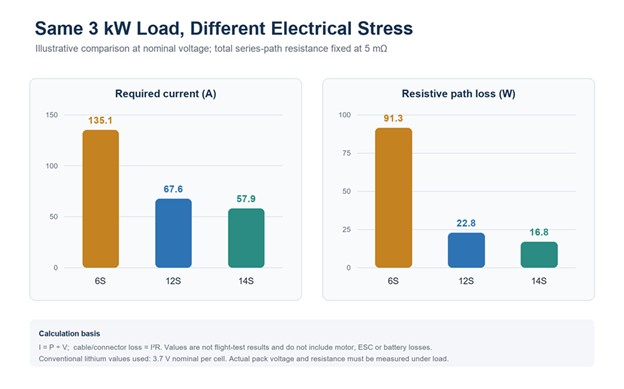
Transparent engineering calculation at the same 3 kW load. Higher voltage lowers current, and the assumed I²R path loss falls much faster than current itself.
Recent research supports treating the cable network as more than an afterthought. Sun and colleagues modelled the battery, propellers, motors, ESCs and transmission cables across a distributed-electric flight profile. Their model errors were below 2%; an optimised cable layout reduced voltage loss by 17.2% and average power loss by 16.36% (Sun et al., 2025). The study did not compare 6S, 12S and 14S directly. Its value here is the system lesson: cable layout can materially change what reaches the propulsion units.
Why a few dozen amps can change the aircraft
Lower pack-terminal and harness current can ease several constraints at once. Connector heating and voltage drop along long arms become easier to control. Parallel cable runs may be reduced and routing simplified. Some designs can then resize the harness after thermal and voltage-drop validation. This does not automatically reduce cell current: per-cell stress still depends on pack energy, series/parallel configuration and cell choice.
Less voltage drop across a fixed-resistance harness can keep ESC input and avionics converters farther from undervoltage thresholds during climb, gust rejection or payload release. This is a distribution-path benefit, not proof that battery sag will fall: pack sag also depends on cell resistance, parallel count, temperature and state of charge. Motor, ESC, battery and DC/DC losses respond differently to operating point, so the propulsion map—not one formula—decides final efficiency.
The right industrial-drone voltage is not the highest S count. It is the voltage at which the whole propulsion and distribution system meets the mission with verified margin.
6S still has a real place
Six-cell packs remain sensible for compact industrial platforms with moderate power, short wiring and a mature 6S propulsion set. Parts, chargers and field procedures are familiar. For a survey aircraft or small inspection multirotor, changing voltage may add integration work without a meaningful mission gain.
Treat sustained three-digit current as an engineering review trigger, not a universal rejection threshold. If a 6S airframe regularly carries 120–150 A, every milliohm matters. Measure connector temperature, contact quality and minimum loaded voltage. More parallel cells can reduce pack resistance and raise capacity, but they add mass; beyond some point, higher-voltage distribution may be the cleaner option.
Why 12S can be a practical industrial middle ground
For multi-kilowatt multirotors, 12S can offer a useful compromise. At the same nominal power, its pack-terminal current is half that of 6S, while full charge remains 50.4 V. This can reduce distribution current without immediately adopting a higher-series-count bus. Motors, ESCs, chargers and auxiliary electronics must still be checked for full-charge voltage, transients and operating margin.
A 2026 experimental study compared 12S LiPo batteries rated at 15C and 20C with a 4,000 W DC generator on a UAV propulsion bench using 24-, 26.5- and 29-inch propellers. The 12S 20C configuration with the 29-inch propeller produced 79.36 N of thrust; the generator produced a comparable 79.17 N at 50.4 V (Hamzah et al., 2026). Those results belong to one test rig and should not be copied into a new aircraft specification. They do show that 12S is being studied as a working high-power bus, not merely discussed as a catalogue upgrade.
A migration from 6S to 12S is never a battery-only swap. A motor wound for 6S may run at an unsuitable speed on 12S; the propeller may move the motor outside its efficient region; the ESC may lack voltage margin; and auxiliary loads may need a different DC/DC stage. The design needs a new motor–propeller–ESC operating map and a fresh minimum-voltage calculation.
Where 14S fits—and what it asks in return
Fourteen cells set the nominal bus at 51.8 V and full charge at 58.8 V. In the illustrative 3 kW calculation, pack-terminal current falls to 57.9 A. That can help heavy-lift designs with long arms or sustained multi-kilowatt loads when conductor loss is the dominant integration problem.
The cost is not only a different charger. Every main-bus device must tolerate full-charge voltage plus credible transients with adequate margin. ESCs, switching devices, connectors, pre-charge or anti-spark hardware, fuses, BMS channels, insulation and DC/DC converters all require review. More series cells also create more measurement points and more opportunities for the weakest cell to define the usable pack window.
No cited source in this article provides an apples-to-apples flight test of 6S, 12S and 14S on the same aircraft. The 14S benefits described here are engineering inferences from the stated constant-power and fixed-resistance assumptions—not a claim of longer endurance.
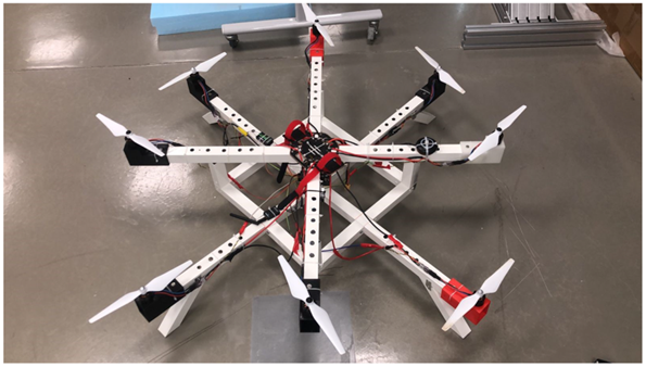
A novel two-layer octocopter prototype. Non-standard airframe and propulsion layouts require the battery, ESCs, motors, wiring and protection hardware to be engineered together. Source: Elhesasy et al. (2024), Drones, CC BY 4.0
Higher voltage does not automatically mean longer flight
This point is easily lost in a sales comparison. If pack energy, aircraft mass and propulsion efficiency are unchanged, raising voltage alone does not add watt-hours. It may reduce distribution-path loss or allow a lighter harness, but those gains must be weighed against ESC losses, motor winding choices, converter overhead, protection hardware and pack construction.
Loaded voltage matters more than the nominal label. Battery resistance changes with temperature and state of charge, and it typically rises in the cold and with ageing. A high-power climb can therefore pull the bus below an ESC or DC/DC threshold before the pack is empty. Di Nisio and colleagues tested UAV LiPo batteries at constant and variable power and reported discharged-capacity prediction errors below 0.7% for their empirical model (Di Nisio et al., 2023). The useful message for procurement is not the model itself. It is that a realistic power profile and measured discharge curve tell us more than nominal capacity.
Altitude and payload can change the answer
A voltage decision that looks comfortable at sea level can become marginal on a plateau. Lower air density increases the rotor speed and power required for a given thrust, while reduced convective cooling changes motor and ESC temperature limits. A 2026 heavy-load UAV study built a dataset of 12,000 synchronised samples. It combined environmental-chamber tests from −10°C to 20°C and 100 to 50 kPa with plateau flights at 2,000, 3,000, 4,000 and 4,500 m carrying 20–50 kg loads (Zhou et al., 2026).
At 4,000 m, the study’s adaptive control method reduced thrust attenuation by about 12.5% and improved energy efficiency by 8.3% compared with the traditional approaches used in the experiment. The authors optimised motor speed, propeller pitch and current limit together. That is exactly why voltage cannot be selected in isolation: the available current, thermal ceiling, propeller operating point and environment are coupled. Higher voltage may help the distribution system, but it cannot correct an undersized propeller or an unrealistic high-altitude thrust margin.
A practical way to choose between 6S, 12S and 14S
The cleanest selection process starts with the mission and works back to the pack. It does not begin with a catalogue voltage. For a new industrial UAV—or a serious upgrade—use the following sequence:
- Measure the load profile. Capture battery-bus power during hover, climb, acceleration, gust recovery and payload operation. Record both sustained demand and peak duration.
- Set the minimum loaded voltage. Use the aircraft’s real undervoltage limits and landing reserve, then include cold temperature, ageing and cell imbalance rather than calculating only from nominal voltage.
- Compare candidate buses. For 6S, 12S and 14S, calculate current, voltage drop, conductor temperature and connector loss across the complete path. Use measured or conservatively bounded resistance.
- Re-select propulsion hardware. Check motor Kv, propeller size, ESC voltage and current margin, switching frequency and cooling at the actual operating points.
- Review every attached device. Confirm full-charge and transient tolerance for BMS hardware, contactors, fuses, anti-spark or pre-charge circuits, chargers and DC/DC converters.
- Validate the aircraft. Repeat bench and flight tests at representative payload, temperature, altitude and wind, and inspect minimum bus voltage, component temperature and reserve at landing.
What industrial buyers should ask a battery supplier
A useful quotation should make the voltage basis explicit. Ask whether the figures are cell-level or pack-level and whether the cells are conventional 4.2 V or LiHV. Request total watt-hours, nominal and full-charge voltage, rated capacity, continuous current, peak current with permitted duration, minimum loaded voltage, operating-temperature range and recommended charging temperature. Capacity and C-rate without a defined temperature and voltage cut-off are not enough.
For an intelligent pack, ask about cell-voltage and multi-point temperature sensing, BMS data logging, cycle count, state-of-health estimation and fault records. Then request realistic discharge and flight evidence: aircraft model, take-off mass, payload, motor and propeller combination, weather and altitude assumptions, peak-current events and landing reserve. A capable custom-battery supplier should be willing to discuss the voltage plan before freezing the pack, because connector, harness, BMS, mechanical envelope and thermal design all depend on it.
The decision is about the whole aircraft
Six-cell systems are not obsolete. Twelve-cell systems are not automatically optimal. Fourteen-cell systems are not a shortcut to endurance. Each can be the right answer when the power level, wiring length, propulsion map, environment and service strategy support it. The mistake is treating S count as a stand-alone battery feature.
For heavier and more highly instrumented industrial drones, it is worth reopening a voltage decision inherited from an earlier airframe. Start with measured mission power, model the complete electrical path, and verify the worst loaded voltage and temperature in flight. The best bus voltage is the one that makes the aircraft easier to prove—not merely easier to advertise.