Two batteries can accept the same plug and still require different chargers. The connector establishes a physical current path. It does not identify the battery chemistry, series count, charge cut-off voltage, permitted current, polarity, balance-pin order, temperature limits or digital communication expected by a smart battery.
For an industrial UAV fleet, charger compatibility must be approved at the battery-model and system-revision level. A buyer should treat the connector as one line in a compatibility matrix, not as evidence that a charger is safe or suitable. This distinction matters when batteries are customized, when fleets mix older and newer packs, and when distributors source chargers separately from the battery manufacturer.
A defensible approval must match eight independent items: charge profile, voltage, current, polarity and pinout, balancing method, temperature control, BMS communication and firmware, and the charger’s AC-input and site-power requirements. A match on one item cannot compensate for a mismatch on another.
A connector solves only the mechanical interface
A main power plug answers a narrow question: can two mating halves make electrical contact? It may also provide a current rating when the exact contact, wire gauge, assembly method, ambient temperature and duty cycle are known. It does not program the charger. The same shell can be installed on packs with different voltages, different polarity or different auxiliary wiring.
Industrial drone packs often expose more than the positive and negative power conductors. A separate balance connector may provide access to each series node. A smart pack may add temperature, wake, identification or communication contacts. Even when these plugs look familiar, the pin order and logic remain part of the pack specification.
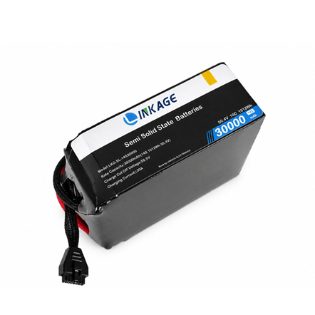
Figure 1. A LINKAGE 14S 30,000 mAh, 1,512 Wh battery for heavy-lift and agricultural UAV platforms. The connector is visible, but the approved specification still defines the 59.5 V charge cut-off, charging-current limit and required charging logic. Product photo and specifications: LINKAGE
Start with the exact charge voltage and chemistry
Lithium-ion charging is commonly controlled through precharge, constant-current and constant-voltage stages, followed by a defined termination condition. The upper voltage is a controlled parameter, not something the connector can reveal. Texas Instruments describes these stages and shows that charging current, regulation voltage, termination and temperature monitoring are separate settings in a charger design. [2] The U.S. Department of Energy likewise describes the CC/CV process and warns that exceeding the intended upper voltage can damage a lithium-ion cell and create a safety issue. [1]
A charger set above the approved pack limit can continue pushing the battery toward an over-voltage condition. A setting below the required limit may stop early or produce an incomplete result. Neither outcome can be diagnosed from the plug shape. The battery supplier should provide nominal voltage, series count, charge cut-off voltage and chemistry or approved charge profile; the charger supplier should confirm that the output regulation and termination logic match those values.
The same series count can still require a different setting
Published LINKAGE specifications provide a useful real-world example using only high-capacity industrial packs. The 6S LKG-SL-6S50000 and LKG-SL-6S72000 models both list a 25.5 V charge cut-off, but their published maximum charging currents are 25 A and 36 A. The 14S LKG-SL-14S30000 lists a 59.5 V charge cut-off and a maximum charging current of 30 A. [6][7][8][9] These catalog values do not state that the packs use the same connector. They show why neither connector appearance nor capacity alone can determine the correct charger settings.
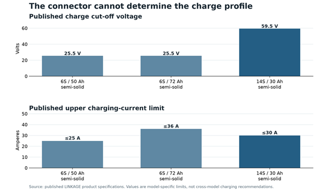
Figure 2. Published charge limits for three large industrial UAV battery models from 30 Ah to 72 Ah. The two 6S packs share the same published cut-off voltage but have different current limits; the 14S pack requires a different voltage profile. These are model-specific catalog limits, not permission to interchange chargers. Data source: LINKAGE product specifications
Charging current must match the pack and the installation
Maximum charging current is also model-specific. The three high-capacity catalog examples range from 25 A to 36 A. A charger that can deliver 36 A is not automatically appropriate for every pack that shares its plug. The configured current must remain within the battery supplier’s approved limit and may need to fall further because of temperature, state of charge, pack age, cell imbalance or site power constraints.
Charger nameplate power deserves a separate check. Multiplying the 59.5 V cut-off and 30 A maximum published for the LKG-SL-14S30000 gives 1.79 kW. That is only an upper-bound product of two catalog limits; a CC/CV charge does not normally hold both values throughout the cycle. It is not a claim about average input power or a recommended charger rating. The actual charger design must include conversion efficiency, AC input limits, thermal derating, simultaneous-channel loading and the manufacturer-approved current schedule.
Input supply can change turnaround even when the battery-to-charger pairing is correct. DJI publishes 992 W output for the BS65 station on 220–240 VAC and 750 W on 100–120 VAC; its laboratory reference for charging two TB65 batteries from 0% to 100% is 60 minutes and 70 minutes respectively. [3] Those figures apply only to the BS65 test conditions, but they illustrate the procurement check: use the exact charger input table, simultaneous-channel limit and generator requirements when planning field throughput.
Polarity and pinout are separate compatibility checks
A physically mating connector does not prove that positive and negative are assigned to the same contacts. Reversed polarity can create an immediate fault before any charging algorithm has a chance to respond. The approved interface drawing should identify connector manufacturer and part number, keying, contact series, polarity, wire size and strain relief. Teams should verify assembled samples against that drawing rather than relying on wire color or a marketplace connector name.
Auxiliary connectors need the same discipline. A balance harness for an unmanaged multi-cell pack normally exposes sequential cell-group nodes. A smart-battery connector may combine voltage sense, thermistor, wake and data contacts. Shifting that pinout by one position can present an unintended voltage to the charger electronics. Adapters should therefore be treated as engineered assemblies with controlled drawings, insulation, current rating and traceability, not as convenience cables.
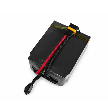
Figure 3. Power and auxiliary interfaces on the LINKAGE 14S 30,000 mAh industrial UAV battery. The connector housings are visible, but their pin assignments, allowable current and charger logic must come from the approved interface specification. Product photo: LINKAGE
Balancing and temperature control must have a defined owner
A multi-cell charger needs to know whether balancing happens in the charger, inside the battery BMS or through a coordinated process. A conventional LiPo pack may depend on the charger reading the balance lead. A smart battery may measure and balance cell groups internally while exposing data to an approved charger. Connecting only the main leads to a generic power source does not establish that cell-group voltages are being monitored.
Temperature creates another model-specific boundary. Tattu’s Smart Battery 3.0 manual recommends charging its listed packs from 10 °C to 45 °C and documents low- and high-temperature charge alarms. [4] The DJI BS65 station provides a different product example: it automatically warms a TB65 after insertion when the battery is below 18 °C. [3] Those values belong to the cited systems. They show why charger behavior can depend on battery temperature; they are not universal limits for every drone battery.
UL Solutions explains that the end-product manufacturer must specify the highest and lowest charging temperatures from the cell limits and that charging safeguards must keep the cell within its specification. [10] For an OEM program, the RFQ should therefore identify the temperature sensor type, location, thresholds, charger response and what happens when the sensor is open, shorted or unavailable.
Smart batteries add communication and firmware compatibility
A smart battery can use communication to report identity, voltage, temperature, state of charge, warnings and allowable current. The charger may use those values to enable output or adjust the charge. A main connector that carries current cannot substitute for that exchange.
DJI states that the BS65 is compatible only with the TB65 and WB37 battery models. Its guide also describes battery-port communication errors and model-specific Storage, Ready-to-Fly and Standard modes. [3] Grepow describes the TA9000 as a 12S-22S LiPo/LiHV charger that reads supported Tattu smart-battery information and adjusts current according to battery status. [5] These examples show that compatibility is a defined relationship between battery, charger, communications and firmware. They do not make either charger a universal choice for another brand or battery family.
For B2B purchasing, ask both suppliers to name the communication protocol, physical data pins, message set, wake sequence, firmware versions and behavior when data are missing or implausible. A pack that charges only after a firmware downgrade, ignores a temperature message or falls back to an undocumented current is not a qualified production pairing.
Build a written battery and charger compatibility matrix
A controlled compatibility matrix prevents a fleet technician from making a decision by plug appearance. It should identify the exact battery model and revision, the approved charger model and firmware, and the interface drawing that connects them. The minimum fields below are practical for an OEM, distributor or fleet operator.
| Compatibility item | Battery supplier should state | Charger supplier should confirm |
| Identity | Model, serial format, hardware and BMS revision | Supported model and permitted revisions |
| Charge profile | Chemistry and approved charging method | Available profile and termination behavior |
| Voltage | Series count, nominal voltage and exact cut-off | Regulation range and accuracy at the required voltage |
| Current | Recommended and maximum current with conditions | Programmable limit, accuracy and thermal derating |
| Power interface | Connector part, polarity, contacts and cable size | Matching part, current margin and reverse-polarity control |
Compatibility matrix continued
| Compatibility item | Battery supplier should state | Charger supplier should confirm |
| Auxiliary interface | Balance, thermistor, wake and data pinout | Pin mapping, sensor handling and isolation |
| Communications | Protocol, message set and fault behavior | Handshake, firmware support and safe fallback |
| Environment | Approved charging-temperature range | Temperature sensing, inhibit logic and cooling |
| Site power | Required turnaround and simultaneous packs | AC input, efficiency, channel loading and generator needs |
Qualify the pairing before fleet release
Compatibility should be demonstrated with representative production hardware, not inferred from a successful one-time connection. Begin with a document review, then conduct controlled bench charging away from the aircraft. Record pack and cell-group voltages, current, temperatures, charger state, BMS messages and termination behavior. Verify connector temperature and inspect the contacts after repeated cycles.
The qualification should also exercise abnormal conditions that the approved system is designed to manage: an out-of-range battery temperature, missing sensor, communication interruption, incorrect pack identity, low pack voltage and loss of input power. Simulate or inject these faults only through a documented test plan and supplier-approved setup. Define the expected result in advance. A protection trip can be the correct result; continuing at an arbitrary fallback current may not be.
Release the pairing by part number and revision. If the battery cells, BMS firmware, connector, pinout, charger hardware, charging algorithm or cable assembly changes, assess whether the qualification remains valid. This change control is valuable for exporters because it prevents a customer from combining a new batch with a charger that was approved only for an older configuration.
What buyers should send with a charger inquiry
A useful inquiry should contain enough information for the supplier to reject an unsafe assumption before quoting. Send the following:
- Battery manufacturer, exact model, configuration, chemistry and capacity.
- Nominal voltage, full-charge or charge cut-off voltage, recommended current and maximum current.
- Photographs plus part numbers for the main connector and every auxiliary connector.
- A controlled pinout showing polarity, balance nodes, temperature sensing, wake and communication lines.
- BMS protocol, firmware version, required charger messages and fault behavior.
- Charging-temperature range, expected ambient range and cooling arrangement.
- Number of packs charged simultaneously, required turnaround time and available AC or generator supply.
- Target markets, applicable documentation and the validation records expected before production release.
For a custom project, the battery and charger should be quoted as a verified combination. If the charger is sourced separately, ask for written confirmation from both parties and retain the approved settings with the production records.
Common charger compatibility questions
If the connector and voltage match, is the charger compatible?
No. Current limit, chemistry, termination, polarity, balance method, temperature sensing and smart-battery communication still need confirmation. Matching the voltage is necessary, but it does not complete the compatibility case.
Can an adjustable hobby charger be used for an industrial drone pack?
Only when the battery manufacturer approves the charger, wiring, profile and settings for that exact pack. An adjustable display does not verify the pinout, BMS behavior, sensor inputs or suitability for repeated fleet duty.
Does the BMS make the wrong charger safe?
The BMS is a protection layer, not a reason to ignore charger compatibility. Protection thresholds, switching devices and fault responses have limits. The normal charge process should remain inside the approved battery envelope without depending on a protective trip.
Is a lower charging current always acceptable?
A lower current may reduce electrical and thermal stress, but it can still conflict with charger timeout logic, minimum-current detection, BMS communication or operational requirements. Obtain model-specific approval instead of treating lower current as universally compatible.
Approve the whole charging interface
The safest procurement decision is also the clearest commercial decision: approve the battery, charger, cables, connector drawings, settings, communications and firmware as one controlled system. A matching connector is useful, but it is only the visible edge of that system.
For an OEM or fleet quotation, provide the battery model, charge cut-off voltage, desired turnaround, connector and pinout, BMS protocol, ambient range and available site power. A supplier can then propose a charger configuration that is technically reviewable instead of guessing from a photograph of the plug.
Sources
Manufacturer and technical sources checked on 16 September 2026. Product limits remain model-specific; use the current approved documents for the exact battery and charger revision.
[4] Grepow Tattu Smart Battery User Manual 3.0, charger type, charging temperature and alarm behavior
[5] Grepow TA9000 smart drone battery charger, supported batteries, voltage range and communication
[6] LINKAGE product catalog, published charge cut-off voltage and maximum charging current
[7] LINKAGE 6S 50000mAh Semi-Solid-State UAV Battery product specification
[8] LINKAGE 6S 72000mAh Semi-Solid-State UAV Battery product specification
[9] LINKAGE 14S 30000mAh Semi-Solid-State Li-ion Battery product specification
[10] UL Solutions IEC 62368-1 engineer Q&A, charging-temperature safeguards and cell limits