Battery headlines usually focus on chemistry: higher energy density, faster charging, longer cycle life and safer electrolytes. Yet every ampere entering or leaving a pouch cell must pass through a much less celebrated component—the tab system. In high-power drone batteries, that narrow current path can influence voltage sag, local heat, usable power and long-term consistency.
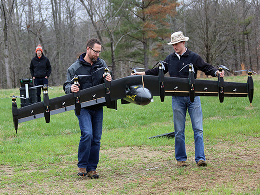
Figure 1. NASA’s battery-powered Greased Lightning prototype shows the type of distributed-electric aircraft in which transient current and pack mass must be managed together. Photo: NASA Langley/David C. Bowman; U.S. government work. NASA Spinoff source
The timing is important. A peer-reviewed study published on 14 July 2026 examined tab position, tab size, cell aspect ratio and multiple-tab arrangements in pouch cells at a modeled 12C rate. Its validated electrochemical–thermal model found the strongest overall performance in multiple-tab layouts, especially when tabs were arranged on opposite sides, because these configurations reduced ohmic losses and produced a more uniform temperature field [1]. The work was not a UAV flight test, but the underlying current-path problem is directly relevant to aircraft that demand large, rapidly changing power.
The overlooked bottleneck inside a pouch cell
A pouch cell is not a uniform block of active material connected to two wires. Its stacked or wound electrodes use metal current collectors—typically aluminium on the cathode side and copper on the anode side. Those collectors converge at external tabs, which are then joined to pack busbars, cables or terminal hardware. The distance current must travel through the collectors, the cross-sectional area of the tabs and the quality of each joint all add resistance.
That resistance is small in absolute terms, often discussed in milliohms or fractions of a milliohm. Small does not mean harmless. A poorly distributed current field can make one region work harder than another. The resulting hot spot changes local reaction rates, accelerates non-uniform ageing and can increase the gap between the hottest and coolest areas of the cell. A laboratory capacity number may remain impressive while the pack delivers less stable voltage under a real propulsion pulse.
Why drone missions expose weak current paths
Industrial UAVs are unusually demanding because propulsion power changes quickly. Vertical take-off, hover, gust rejection, payload manoeuvres and landing reserves create a mix of sustained and peak loads. Consider a transparent engineering example: a 12-series pack with a nominal voltage of 44.4V supplying 10kW would carry about 225A before accounting for voltage sag or conversion losses. A 25Ah cell string at 200A is operating at 8C. These are calculations, not specifications for a particular aircraft, but they show why tab geometry cannot be treated as packaging detail.
The same current passes through every cell in a simple series string. Adding more series cells raises voltage, but it does not divide string current. Parallel paths can share current, yet only when cell, tab, weld and busbar resistances are sufficiently matched. If one parallel path has more resistance, current sharing becomes uneven and the apparently redundant design can develop a dominant hot branch.
The milliohm problem: heat grows with the square of current
Resistive heat follows P = I²R, while voltage loss follows V = IR. Doubling current therefore doubles the voltage drop but quadruples heat. The table below uses hypothetical total tab-and-interconnect resistances of 0.5mΩ and 1.0mΩ. It is an engineering illustration, not test data for any product.
| Current | Heat at 0.5mΩ | Heat at 1.0mΩ | Voltage drop at 1.0mΩ |
| 50 A | 1.25 W | 2.50 W | 0.05 V |
| 100 A | 5.00 W | 10.00 W | 0.10 V |
| 150 A | 11.25 W | 22.50 W | 0.15 V |
| 200 A | 20.00 W | 40.00 W | 0.20 V |
Calculation basis: P = I²R and V = IR. Resistance values are illustrative and do not describe a named cell or pack.
Engineering takeaway: At 200A, a 1.0mΩ path converts 40W into concentrated heat. Reducing resistance by only 0.5mΩ halves that local loss.
What the latest research actually shows
A 2026 model study at 12C
Chansiriwat and colleagues compared tab position, size, aspect ratio and multiple-tab arrangements using a validated electrochemical–thermal model. At 12C, their multiple-tab configurations reduced ohmic losses and improved temperature uniformity; arrangements with tabs aligned on opposite sides performed particularly well. The study also included a cost-performance assessment and identified a multiple-tab design as the most promising overall configuration [1].
The scientific boundary matters. The published abstract does not establish a universal percentage improvement for every pouch chemistry, capacity or UAV pack. It also does not prove a flight-time gain. What it supports is more precise: current-collection geometry can materially change cell-level electrical and thermal behaviour under high-rate operation.
A separate 3D optimization study offers a longer-term signal. For its modeled 45Ah LFP pouch cell, the optimized combination of tab type, attachment position and cell aspect ratio produced 7.3% less discharge-capacity reduction than the initial design after 1,000 simulated cycles; average SEI-film resistance was 8.2% lower [4]. These are model-specific results rather than a universal life-extension claim, but they show why thermal uniformity can matter beyond a single high-current pulse.
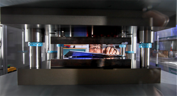
Figure 2. A researcher examines a pouch cell in an R&D manufacturing facility at Oak Ridge National Laboratory. Cell geometry, sealing, compression and current collection must be controlled as one manufacturing system. Photo: U.S. Department of Energy; public domain. DOE photo source
Experimental evidence: the tab area gets hot
A separate 2026 study provides useful experimental context. Researchers instrumented a 3.7V, 57Ah pouch cell with thermocouples, heat-flux sensors and thermal imaging, then tested it from 0.5C to 2C. Their model agreed with measured maximum temperatures with an average deviation of about 4.54%. The hottest area was around the tabs. At higher rates, heat originated more strongly near the tab region; the top of the cell ran hotter than the bottom, with reported face-temperature gradients of 2–4°C [2].
Measured maximum temperature increased from 29.7°C at 0.5C to 39.4°C at 2C. The model projected 48.51°C at 4C and 54.02°C at 5C, but those two high-rate points were not experimentally measured in that paper. The chart preserves that distinction instead of presenting all six points as equivalent evidence.
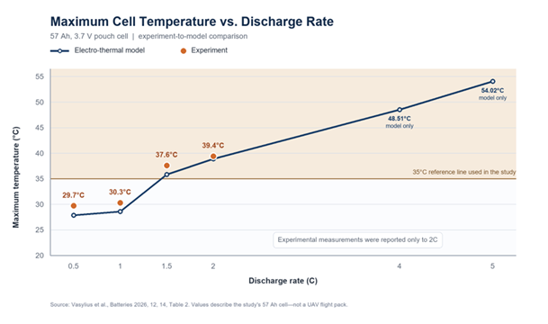
Figure 3. Maximum temperature versus discharge rate for the 57Ah pouch cell. Orange points are experiments; blue points are electro-thermal model results. The 4C and 5C values are model-only and are not UAV flight-pack data. Data source
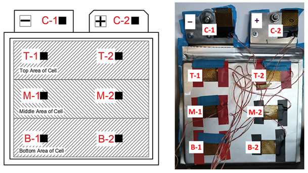
Figure 4. The 57Ah pouch-cell sensor layout and physical test article. The real photograph on the right shows the two terminal areas and six face sensors used to study non-uniform heating. Reproduced from Vasylius et al., Batteries 2026, Figure 1, under CC BY 4.0. Open-access source
Five geometry choices that change thermal behaviour
1. Tab position and symmetry
When positive and negative tabs sit on the same edge, packaging and external connection can be convenient, but current may travel farther through parts of the collectors. Opposite-side or counter-tab layouts can shorten and balance in-plane current paths. Earlier 3D studies of large pouch cells also found that symmetrical configurations produced more uniform potential, current-density and temperature distributions [6].
2. Tab width
A wider tab generally reduces current density and conductor resistance, but it occupies seal-edge area, adds material and changes the weld design. A 2022 statistical study of a modeled 55Ah LFP pouch cell found that wider tabs reduced both maximum temperature and temperature difference across nominal, lateral and counter-tab configurations [5]. The optimum is therefore constrained by cell size, laminate sealing, weld access and mass—not electrical resistance alone.
3. Tab height and unsupported length
Making a tab larger in every direction is not automatically beneficial. The same 2022 analysis reported that taller tabs increased maximum temperature and temperature difference within its studied geometry [5]. External tab length also affects stiffness, vibration response and the location of heat generation. In an aircraft pack, the mechanical design must prevent the weld or seal edge from carrying cable loads.
4. Number of collection points
Multiple tabs divide current collection across the electrode stack and can reduce long in-plane paths. Research on large-format cells has shown that this can recover usable performance otherwise lost to ohmic drop and non-uniform active-material utilisation [7]. More collection points, however, create more welds and more opportunities for mismatch. Current sharing must be verified, not assumed.
5. Cell aspect ratio
The distance from any point on the current collector to a tab depends on cell width and height. A 2020 study of a modeled 55Ah pouch cell found its lowest temperature standard deviation at an aspect ratio of 2.15 with positive and negative tabs on opposite sides [3]. That number is not a universal design target; it belongs to the paper’s cell and boundary conditions. The broader lesson is that tab design and cell shape must be optimized together.
More tabs are not automatically better
A multiple-tab cell can reduce electrical loss while making manufacturing and pack integration harder. Each additional tab requires precise alignment, joining and insulation. Weld-area variability can offset the theoretical benefit. More metal also consumes mass and volume, while opposite-side tabs may complicate busbar routing, thermal interfaces and serviceability.
The correct comparison is therefore not ‘single tab versus multi-tab’ in isolation. Engineers should compare the complete current path: collector foil, tab weld, external tab, busbar, fuse, connector, cable, BMS shunt and return path. A cell with excellent internal collection can still be compromised by a high-resistance pack joint. Conversely, a carefully designed pack cannot fully correct a current-density hot spot built into the cell.
Chemistry cannot fix a poor current path
The principle applies across conventional liquid-electrolyte, silicon-anode and semi-solid pouch cells. Higher specific energy can reduce battery mass for a given watt-hour target, but it does not remove the need to move electrons through metal collectors and tabs. If a higher-energy cell is also asked to deliver more current from a similar tab envelope, current density may rise unless the collection structure is redesigned.
This is why cell-level Wh/kg, nominal C-rate and cycle count should not be evaluated separately from geometry. For a long-endurance UAV, the dominant question may be energy. For a heavy-lift multirotor, pulse power and voltage stability may matter just as much. A credible supplier should map chemistry, electrode design, tab geometry and pack interconnects to the aircraft’s actual mission profile.
A credible UAV validation plan
Published models are valuable for screening designs, but a flight pack needs its own evidence. At minimum, a development programme should include the following checks:
- Measure cell and pack DC resistance at defined state of charge, temperature and rest time. The method and pulse duration must be reported so results are comparable.
- Apply the real continuous and peak-current profile, including take-off, hover, manoeuvre and landing reserve. A single constant-current discharge misses mission transients.
- Map temperature on both pouch faces, at each tab, across welds and at the pack connector. Report the hottest point and cell-to-cell spread, not only one central sensor.
- Record voltage sag and recovery at cell level. A pack-level voltage trace can hide one weak cell or an unbalanced parallel path.
- Verify weld resistance, mechanical pull strength and process repeatability. Samples should include beginning, middle and end of production runs.
- Repeat pulse and thermal tests after ageing, vibration and compression exposure. Swelling and joint fatigue can change the current path over time.
- Finish with aircraft testing that states model, take-off mass, payload, weather, flight mode and landing reserve. Endurance claims without those conditions are not transferable.
What buyers should ask before approving a custom pack
Ask whether the quoted discharge capability is cell-level or pack-level. Request total watt-hours, nominal voltage, rated capacity, continuous current, peak current and the permitted peak duration. Then ask for DC resistance, voltage sag and temperature maps at the intended current—not only at 1C or room temperature.
For the tab system, request a drawing or controlled description of tab position, width, material, weld method and busbar interface. Ask how resistance is checked in production and how abnormal joints are rejected. If the design uses parallel cells or parallel packs, request evidence of current sharing. If the supplier calls the pack ‘high rate’, the evidence should include pulse data, thermal data and a stated end-of-discharge limit.
Finally, separate model results from experiments and laboratory tests from flight tests. A model can rank concepts efficiently. A bench test can reveal thermal behaviour. Only a controlled aircraft test can establish mission-level endurance and reserve. Each layer answers a different question, and none should be presented as a substitute for the others.
The next design frontier
Pouch-cell tab design is likely to become more important as UAV batteries move toward larger cells, higher energy and more aggressive power pulses. Future packs will increasingly combine electrochemical–thermal modelling with automated weld monitoring, multi-point temperature sensing and production traceability. The most capable designs will co-optimize cell aspect ratio, tab layout, busbar geometry and cooling interface instead of treating them as separate supplier decisions.
For drone manufacturers, the buying question changes. The best battery is not the cell with the highest printed C-rate. It is the system that delivers the required current with controlled voltage drop, limited temperature spread and repeatable joints after ageing, vibration and flight exposure.
Conclusion
The tab is a small part with system-level consequences. Recent modeling supports multiple, well-positioned tabs for reducing ohmic loss and improving thermal uniformity at high rate. Current experimental work confirms that pouch-cell heating can concentrate around the tab region and rise sharply with discharge rate. Neither result proves a universal flight-time gain, but together they make a strong engineering case: high-power UAV battery design must begin with the complete current path, not chemistry alone.
For buyers and aircraft developers, the practical standard is straightforward—demand geometry-aware design, transparent resistance and thermal data, and flight tests tied to a defined mission. Milliohms are easy to ignore on a specification sheet. In the air, their heat and voltage loss are much harder to hide.